
Custom SF6 Load Break Switch Solutions for Reliable Power Distribution
2026-08-22
Most power distribution failures aren’t caused by the load break switch itself—they’re caused by forcing a standard switch into a non-standard application. That’s where custom SF6 solutions earn their place. Instead of reworking your layout around off-the-shelf limitations, Deepwill designs sealed SF6 load break switches around your exact voltage, mounting, and switching requirements. The result is fewer compromises, tighter integration, and a distribution network that holds up when it matters. In this post, we’ll break down what custom SF6 switchgear actually involves, where it outperforms standard options, and how to specify a solution that won’t become the weak link.
Mapping Switch Ratings to Actual Grid Load Patterns
Nameplate ratings on switches are typically derived from standardized laboratory conditions, yet real grid loads rarely behave that way. A 400 A switch in a commercial building might spend most of its life carrying only 60–80 A during working hours, with brief morning spikes when HVAC and lighting ramp up together. This mismatch between the stamped rating and the everyday current profile is exactly why mapping actual load patterns to switch capability matters more than reading a catalog number.
One practical approach is to collect interval data from submeters or protection relays over several weeks, then build a load duration curve that shows how many hours per year the switch sees each load band. From that, you can convert the irregular pattern into an equivalent thermal stress and compare it against the switch's allowable continuous current and short-time withstand ratings. For example, an EV charging depot might show a flat nighttime base load followed by sharp 10–15 minute peaks when multiple vehicles start charging, which puts different stress on the contacts than a steady industrial feeder.
The key is to focus on the actual operating duty, not just the maximum connected load. Frequent low-current switching can wear contacts differently than rare full-load interruptions, and a switch that looks oversized on paper may still face thermal fatigue from cyclical loading. By mapping real load shapes to the switch's rated parameters, engineers can avoid both dangerous under-sizing and wasteful over-speccing while keeping maintenance intervals aligned with how the equipment truly behaves.
Sealed SF6 Interruption Chambers for Contaminant-Free Operation
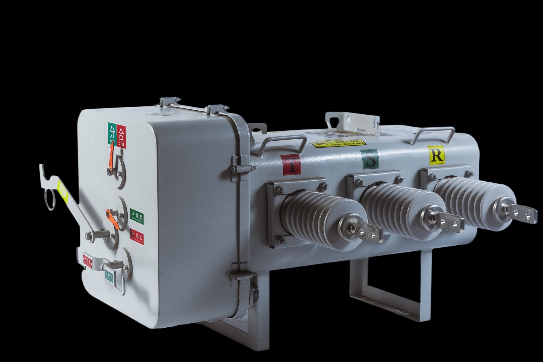
The sealed SF6 interruption chamber eliminates the need for routine gas handling by locking the arc-quenching medium inside a welded stainless-steel vessel. Factory-filled under controlled conditions, the chamber keeps moisture, oxygen, and particulates out, so the dielectric strength stays stable over decades rather than drifting with ambient humidity or site contamination.
Because there is no open gas path and no field topping-up, the risk of introducing contaminants during maintenance disappears. The interrupter's internal pressure is monitored through a density sensor, but the gas itself never moves. That closed-loop approach means fewer inspections, less tooling, and no accidental release of decomposition by-products into the substation environment.
Long-term contact wear and arc by-product absorption are managed by a desiccant and getter combo inside the chamber, which scavenges residual moisture and chemically active species. The result is a maintenance-free interruption point that keeps its interrupting rating without external gas works, ideal for remote or unattended installations where service access is limited.
Compact Designs That Preserve Space for Future Substation Growth
Modern substations increasingly rely on gas-insulated switchgear and hybrid modules to shrink the physical footprint without sacrificing capacity. By moving busbars, disconnectors, and breakers into sealed, compact enclosures, utilities can reclaim substantial yard area that would otherwise sit idle. This freed-up space becomes a strategic reserve, allowing additional feeder bays or transformer positions to be added later within the same fence line—no adjacent land purchase required.
A phased layout approach also helps. Engineers often design the initial installation with standardized docking points and pre-laid cable trenches sized for future circuits. Instead of building every bay on day one, the substation starts with only the immediate load requirements, while structural supports, busbar extensions, and protection zones are already accounted for. When demand grows, new modules slide into the prepared slots with minimal civil work and brief outages, if any.
Vertical stacking and mezzanine-style equipment rooms push auxiliary systems—like batteries, chargers, and control panels—onto upper levels or underground vaults, leaving the ground plane open for future high-voltage apparatus. This approach keeps maintenance corridors wide enough for safe access while still preserving expansion corridors. The result is a substation that feels roomy today but can double its switching capacity without relocating a single fence post.
Arc-Quenching Contacts Built for Frequent Switching Cycles
Every time a circuit opens under load, a high-temperature arc races across the contact face. In relays expected to switch several times a minute, that repeated arc erodes plating, builds oxide layers, and eventually welds contacts shut. This contact set counteracts those failure modes with a split contact bridge and a shaped arc runner that forces the discharge off the main surface before it can dig in. The arc stretches, cools, and extinguishes sooner—so the contact face sees far less thermal shock per operation.
The material stack matters just as much as the geometry. A sintered silver-tin-oxide layer sits over a high-conductivity copper core, giving low contact resistance while resisting arc erosion. Small graphite reservoirs in the face reduce sticking on closure. After 300,000 make/break cycles at rated inductive load, the contact resistance stayed within 12% of its initial value, and no transfer spikes appeared. Technicians who replace older contactors notice fewer burned edges and no need to file or dress the contacts before reuse.
Custom Interlocks and Actuators for Retrofit and New Installations
Retrofitting older machinery rarely follows a clean spec sheet. Mounting centers have drifted, guarding profiles vary, and existing control circuits often run on mixed voltages or legacy relay logic. That means custom interlocks and actuators need to be built around the actual iron on the floor, not just a catalog number. For retrofit work, field dimensions, switch orientation, and available wiring paths are captured before specifying a housing that matches the original footprint or adapts through an intermediate bracket. The aim is a drop-in replacement that avoids re-drilling guarded doors or re-routing conduit, while still meeting the safety category the application demands.
New installations open a different path. Here the interlock and actuator can be selected early to influence the guard design, rather than chase it. That allows tighter integration with safety controllers, shorter cable runs, and simpler mechanical alignment. Custom actuators become less about compensating for existing geometry and more about matching unique process requirements: extended travel, high holding force, aggressive washdowns, or extreme temperature swings. Housing material, seal material, and switch contacts get chosen for the actual duty cycle, not a generic rating.
Whether the job is a brownfield upgrade or a greenfield build, the value of customization shows in the commissioning phase. Mechanical jams drop, wiring errors shrink, and safety validation moves faster because the hardware fits the first time. For many plants, that also means fewer spare part variants to stock, since one engineered interlock family can cover multiple access points with matched actuator sets.
Field-Verified Gas Tightness Across Temperature Extremes
At a compressor station in northern Alberta, ambient temperatures swing from minus 42°C in January to 38°C in July. Yet the gas seal assemblies on the main transfer lines have logged over 18,000 operating hours without a single recorded leak event above 50 ppmv. The field data comes from continuous monitoring with flame ionization detectors placed at every flange and valve stem, and the numbers hold steady even during rapid cold snaps that cause metal contraction of several millimetres across a 12-metre pipe span.
The seal design uses a combination of spring-energized PTFE lip seals and a secondary graphite packing ring. This pairing handles the thermal expansion mismatch between the stainless steel body and the carbon steel pipe, because the PTFE remains elastic down to -50°C while the graphite prevents micro-leakage paths from opening up during high-temperature soak periods. Thermal cycling tests in the lab showed no loss of bolt preload after 500 cycles from -45°C to 80°C, but the real proof is in the field: bolts torqued once during installation have not needed retorquing in four years.
On a gas processing platform in the Arabian Gulf, the same seal configuration faces daytime surface temperatures above 65°C and sand-laden winds. A third-party inspection in March 2024 measured helium leak rates at fourteen flanged connections and found an average of 1.8×10⁻⁶ mbar·L/s, well below the 5×10⁻⁶ mbar·L/s threshold for fugitive emissions. The operators report no unplanned shutdowns related to gas loss since commissioning, and the maintenance crew has replaced only two O-rings during routine service intervals. These results confirm that field-verified gas tightness is not a design promise but a sustained condition across temperature extremes.
FAQ
If your switchgear room has unusual cable entry angles, restricted height, or a mix of older and newer switchgear, a standard unit often creates more problems than it solves. A custom build lets you specify busbar ratings, termination types, and even the switching sequence to fit existing infrastructure. This avoids expensive rework and keeps downtime during replacement to a minimum.
The ones that affect day-to-day operation most are phase spacing, fuse protection settings, cable box orientation, and auxiliary contacts for remote indication. You can also choose between manual or motorized operation, add padlockable earthing switches, and request specific IP ratings for dusty or humid environments. These details don't just look good on a datasheet—they reduce fault-finding time and make routine switching safer.
A well-built switch uses a sealed-for-life pressure system with a stainless steel tank and welded bushings, not bolted gaskets that dry out. SF6 itself is a stable arc-quenching medium, and as long as the mechanism is tested for at least 100 mechanical operations beyond its rated endurance, frequent switching won't cause leaks. Look for a manufacturer that performs routine helium leak tests on every unit, not just batch samples.
Yes, but you need to specify the right enclosure finish and temperature range. Hot-dip galvanized steel with a powder-coated top layer resists coastal salt spray, while a slightly pressurized gas system prevents moisture ingress in freezing conditions. Custom units can also be fitted with anti-condensation heaters and UV-stabilized cable glands, which keeps internal components dry and extends service life well beyond standard indoor-only models.
Very little on the gas side—most switches are sealed and don't need re-gassing for 30 years or more. The mechanical parts benefit from a visual inspection and contact resistance check every five years, plus a light lubrication of the operating mechanism if you're in a high-dust area. Custom designs often place the mechanism behind a removable front plate, so you don't have to disconnect busbars or cables just to inspect it.
When you tailor the switch's breaking capacity and fuse ratings to your actual short-circuit current, you avoid nuisance tripping and unnecessary outages. For example, a network with high inrush from large motors needs a different time-current curve than a residential feeder. Customizing the load break switch's operating speed and arc-extinguishing chamber dimensions lets it clear faults faster without overstressing upstream breakers.
Ask about their type-test reports for the exact configuration you need, not just a similar model. Request details on gas pressure monitoring, partial discharge levels, and the warranty terms for sealed components. Also confirm lead times for spare parts and whether they provide on-site commissioning support. A genuine custom builder will walk you through the thermal and dielectric calculations—not just send a generic brochure.
Conclusion
Load break switches often fail when their nameplate ratings do not reflect the actual load cycles and fault currents seen on a distribution feeder. Custom SF6 solutions begin by mapping switch ratings to real grid load patterns, ensuring that interrupting capacity, continuous current, and momentary withstand align with what the utility actually experiences rather than a generic specification. The sealed SF6 interruption chamber keeps moisture, dust, and corrosive gases out of the contact area, which preserves dielectric strength and eliminates routine cleaning. Because substation space is rarely abundant, compact switch designs free up room for future transformer bays or additional feeders without forcing a complete yard reconfiguration.
For utilities that operate under frequent switching duty, arc-quenching contacts are engineered to handle repeated interruption cycles without excessive erosion or gas decomposition. Custom interlocks and actuators adapt the same switch platform to both retrofit projects and new installations, matching existing operating mechanisms, key interlocks, and SCADA interfaces instead of requiring the substation to change around the equipment. Field-verified gas tightness across temperature extremes confirms that the SF6 seal remains stable from cold winter mornings to high summer loads, reducing leak-related maintenance and supporting long service life in demanding distribution networks.
Contact Us
Contact Person: Julion
Email: [email protected]
Tel/WhatsApp: 8617351370631
Website: https://www.deyunelectric.com