

Custom CNC Milling Parts for Precision Manufacturing and Complex Designs
2026-11-17
When a design keeps engineers up at night, it is usually because the part looks simple on screen but turns hostile at the spindle—tight radii, thin walls, awkward undercuts. Custom CNC milling parts close that gap, but only when precision manufacturing is treated as more than a tolerance table. At Tianyu, complex designs are machined with an eye for how chips evacuate, how tools deflect, and how the final surface has to perform. This guide walks through what actually matters when standard catalogs fall short and geometry refuses to compromise.
When the Part Shape Fights the Fixture
A cast bracket rarely sits on the fixture the way its CAD model suggests. The machined datum pads are still as-cast, draft angles cause the clamp to slide, and the part rocks on three locators just enough to push a later bore a few tenths off position. That error shows up at inspection, but it starts when the part geometry refuses to agree with the fixture layout.
Thin-walled parts create a different kind of fight. A clamp near an open edge can pull the wall inward while the tool cuts a round hole; once the fixture releases, the wall springs back and the hole goes oval. The fixture was rigid enough, but the local stiffness of the part was never part of the clamping plan.
Some shapes simply leave no clean place to hold. Organic outer surfaces, ribs, and raised lettering force locators to balance on high spots. A practical move is to stop forcing a conventional rest pad pattern and instead add a temporary datum boss, pot the part in a low-melt alloy, or use vacuum and contour clamping until a stable reference face is machined.
Toolpaths Built Around Thin Walls and Deep Cavities
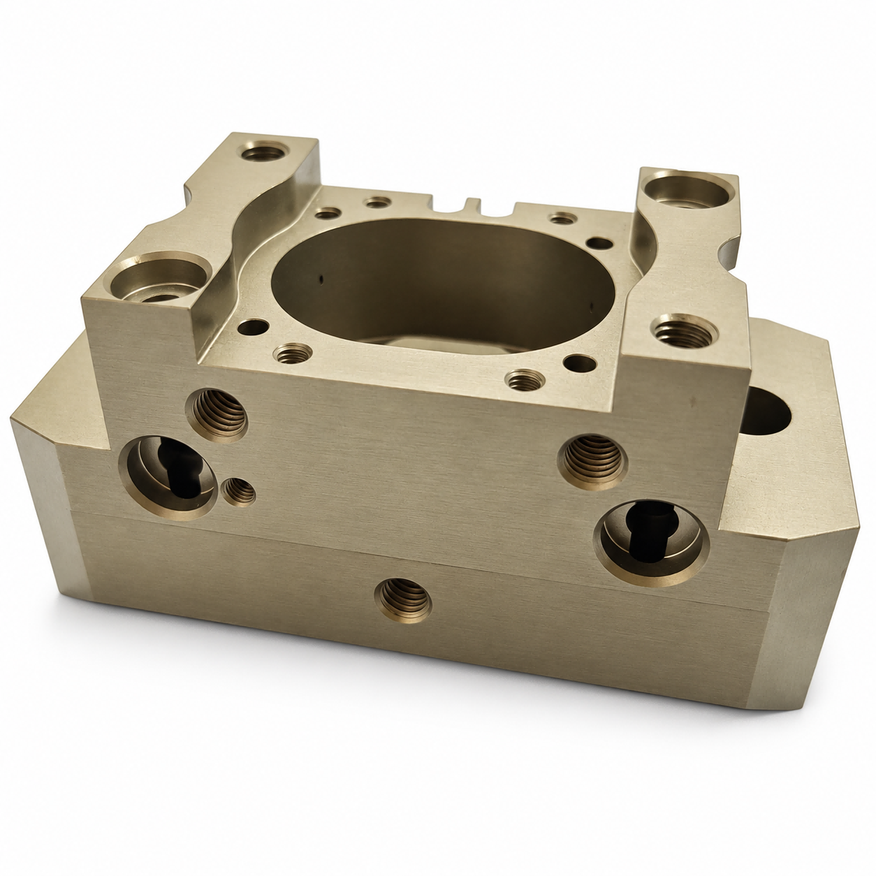
Thin walls rarely forgive a generic approach. A toolpath that treats a 0.8 mm standing rib like a solid block invites chatter, deflection, and snapped tools, so the passes get reordered and the entry points move away from unsupported edges. Where possible, the cutting direction follows the wall’s long axis, and stepovers shrink before the wall loses its surrounding material.
Deep cavities bring a different constraint: the tool reaches farther than it can stay rigid. Instead of plunging straight into a pocket, the paths use helical or ramp entries that keep the cutter engaged at a shallow angle. Chip evacuation matters just as much as geometry here; shorter pecks and occasional retractions become part of the toolpath rhythm, especially when the cavity narrows toward the bottom.
Where the two features meet, the sequence stops being two separate strategies. Thin walls often border deep cavities, so the passes alternate between roughing the open volume and leaving enough stock to brace the wall. That leftover material acts like a temporary fixture, and the finishing passes take it down only after most of the stress has already been released from the part.
Tolerances That Survive After the Vise Releases
When the vise finally releases, most machinists assume the battle is over. But certain tolerances quietly buckle, twist, or drift the moment clamping pressure disappears. Thin-walled parts often spring back by a few tenths, while deep pockets can reveal unexpected taper once the jaws let go. Recognizing which features stay stable and which ones breathe after unclamping separates a careful setup from a lucky one.
The real trouble usually shows up in flatness and parallelism, especially on parts with uneven cross-sections. A plate that measured dead flat under load may crown or cup slightly once free. The same applies to bores that were round during machining but inch toward oval as internal stress redistributes. If you are chasing sub-thousandth work, plan for this release phase instead of treating it as an afterthought.
A practical approach is to rough aggressively, then take a light finishing pass with minimal clamping force. Some shops go further and bolt or adhere the part to a fixture plate, accepting that the final cut happens in a nearly free state. Checking the part an hour after unclamping, not just seconds later, reveals how much those tolerances genuinely survive.
Material Decisions Tied to Stress, Not Just Machinability
Many shops default to machinability ratings when selecting a workpiece material, but that single metric rarely tells the whole story. The real question is how the finished part will behave under load. A free-machining alloy might cut beautifully, yet introduce an unacceptable risk of stress corrosion cracking or premature fatigue in service. Conversely, a tougher steel that slows down the lathe can deliver far longer life where cyclic stress or thermal shock dominates.
Service conditions reshape the priorities. Components exposed to repeated bending, vibration, or pressure spikes need materials chosen for yield strength, ductility, and crack resistance rather than chip formation alone. In those cases, chasing a lower cycle time can quietly undermine the part's core function. The best decisions balance what happens at the spindle with what happens after installation, treating machinability as a constraint rather than the headline requirement.
That shift in thinking also affects prototyping and small-batch work. A material that resists machining may force slower feeds and more frequent tool changes, but if it prevents a field failure or extends maintenance intervals, the trade-off makes sense. Evaluating stress paths early helps avoid the costly loop of redesigning around a material that was never fit for the actual load case.
Complex Contours Without Endless Setup Adjustments
Most multi-axis machining workflows treat every new contour as a reason to stop, re-indicate, and re-tune the entire setup. That habit quietly eats hours and introduces the kind of small misalignments that show up later on tight-tolerance surfaces. The goal here is to get the toolpath to follow complex geometry without forcing the operator into a loop of fixture tweaks and offset corrections every time a wall angle or pocket floor changes.
A more practical route starts with consolidating reference features. By probing a small set of stable surfaces once and letting the control map the rest of the part from that single coordinate frame, you remove most of the repeated setup gymnastics. Combined with shorter, stiffer tool assemblies and toolpaths that stay within the machine's most repeatable travel zones, the process becomes less about fighting the fixture and more about letting the geometry guide the cut. The result is a cleaner surface finish and fewer surprises during inspection.
That shift also changes how operators think about problem-solving on the floor. Instead of chasing dial indicators after every part change, they spend more time watching chip formation and tool wear. When a contour does need adjustment, the correction is usually a small parameter tweak rather than a full re-indication, because the original setup was built to stay coherent across the entire feature set.
Low-Volume Runs Where the First Part Sets the Standard
In a low-volume run, the first piece off the machine is not a formality—it is the standard. There is no large sample to average out a bad offset or mask a dull tool. If that first part measures high on a bore or carries a rough finish, the next ten or fifty parts will carry the same signature. A shop that treats the first article as the baseline can correct a setup before material turns into scrap, and the rest of the run simply follows the tone it sets.
That first part also gives the operator a clear read on things inspection reports rarely capture: how the material responds, whether the coolant is reaching the edge, and how the fixture holds under cutting load. These details show up early, before the run settles into a rhythm. Catching them right away means a short-run job keeps the predictability of a longer series without the bloated batches or the waiting around for a rejected lot.
FAQ
Typical tolerances sit around ±0.005 inches, and tighter fits down to ±0.001 inches are possible depending on the feature and material. If a design calls for something more demanding, we will review the drawing first and confirm what is realistic before cutting starts.
Aluminum alloys like 6061 and 7075 are the most common, followed by stainless steel, brass, titanium, and a range of engineering plastics such as PEEK and acetal. The choice usually depends on how the part will be used, its weight target, and the environment it sits in.
For tough profiles we combine 3-axis and 5-axis milling with custom fixturing, and sometimes split a part into stages to reach undercuts or deep pockets without losing accuracy. The programmer adjusts toolpaths based on the actual shape rather than forcing a standard approach onto every feature.
Yes, low-volume prototypes and larger production batches are both handled in-house. Prototypes often go through a quicker setup process, while production runs get dedicated fixtures and staged inspections to keep everything stable as quantities increase.
Common options include as-machined, bead blasting, anodizing, passivation for stainless steel, and powder coating. If you need a specific cosmetic or functional result, it helps to mention the end use so the right post-processing is matched to the part.
We use a mix of in-process checks, final inspections, and repeatable workholding so the first part and the last part in a batch come out the same. For critical dimensions, reports can be included with the shipment instead of assuming the run stayed within spec.
Yes, STEP, IGES, and PDF drawings are all accepted. A fully dimensioned drawing is useful for quoting and inspection, while a STEP file gives the cleanest path for programming the toolpaths.
Most simple parts ship within one to two weeks, while complex or heavily post-processed parts can take three to four weeks. Material availability plays a big role, so lead time is confirmed during quoting rather than guessed ahead of time.
Conclusion
Custom CNC milling rarely rewards a rigid approach. When the part shape fights the fixture, holding it becomes a design problem in itself. Soft jaws, sacrificial supports, and off-center clamping often matter more than spindle speed. Toolpaths have to be built around thin walls and deep cavities, with light radial engagement, ramped entries, and rest machining so slender sections don't chatter or deflect. The real test comes after the vise releases. A dimension that looked good under clamp load can shift once internal stress relaxes, so roughing, stress relief, and finishing sequence become part of holding tolerance.
Material choice follows the same logic. Stress behavior, not just machinability, decides whether a pocket stays flat or curls after cutting. Complex contours are approached with combined setups and indexed probing rather than endless manual adjustments, which keeps blend lines clean across angled features. Burr control and corner blending are handled in the same operation, not as secondary fixes. In low-volume runs, the first part sets the standard. If it passes inspection with stable offsets and documented tool wear, the next few can be produced without chasing variation. That kind of process control turns custom milling into repeatable precision work instead of a series of one-off corrections.
Contact Us
Contact Person: Vera Yao
Email: [email protected]
Tel/WhatsApp: 8618512832770
Website: https://www.tianyucnc.com